When you are welding, you need clear instructions, and that’s where the welding symbol gives that clarity. It is a directive, telling you exactly what type and technique the welder should employ.
Weld symbols can be complicated to understand, so here are the basics of how to read them.
Key Takeaways
- Welding symbols provide clear instructions on the type and technique of welding required.
- There are 10 basic welding symbols, but many variations and additional instructions can be added.
- Welding symbols include an arrow, reference line, and optional tail to denote specifics of the welding technique or filler material.
- Understanding welding symbols helps welders be more efficient, knowledgeable, and accurate in their work.
How Many Welding Symbols Are There?
There are 10 basic welding symbols as denoted on the chart below.
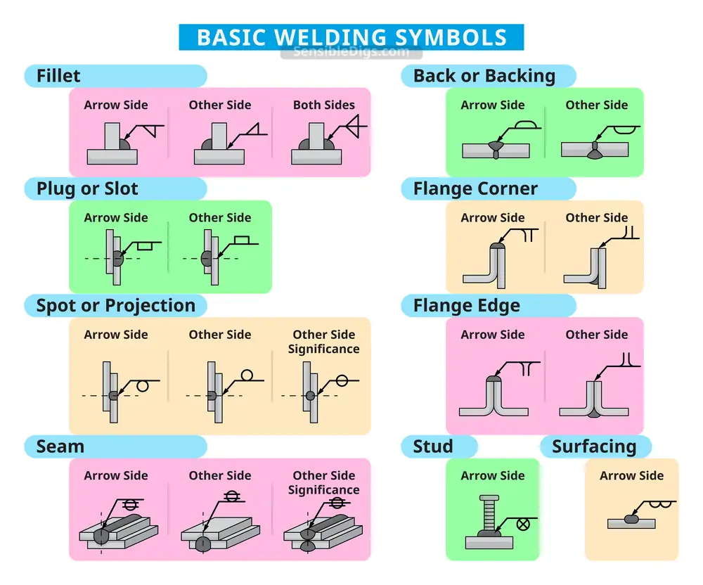
However, while there may be 10 basic symbols, hundreds of variations and additional instructions can be added.
How To Read Welding Symbols
Understanding the welder’s shorthand is crucial if you want to decipher the symbols accurately. Knowing what each element of the shape means is imperative if you want to deliver the project accurately and to specification.
Structure of a Welding Symbol
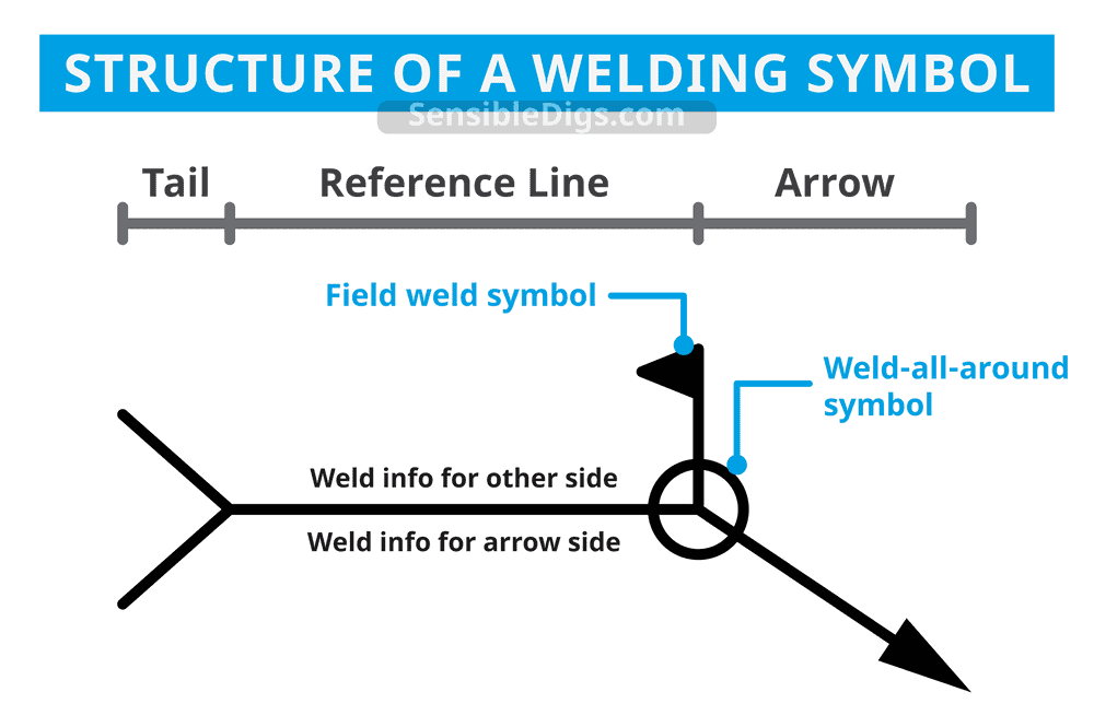
Every welding symbol has an arrow to point to the spot where the weld is to be carried out. Additionally, the arrow is attached to a leader line and a horizontal line called the reference line.
This is the anchor that all other symbols are tied to. The arrow can go in any direction, as shown below, and often there are two directions attached to the reference line, indicating two potential sites to start the weld from, known as “both sides.”
The side with the arrow is known as the “arrow side,” denoting the side the weld is going. The other side is called, rather imaginatively, “the other side.”
The flag indicates that the weld is to be carried out on site. It is known as the field symbol.
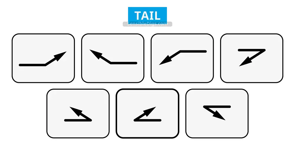
The final piece of the symbol is the tail, which looks like a sideways V. The tail is an optional part of the symbol, reserved for specific instructions like the type of electrode or the welding process.
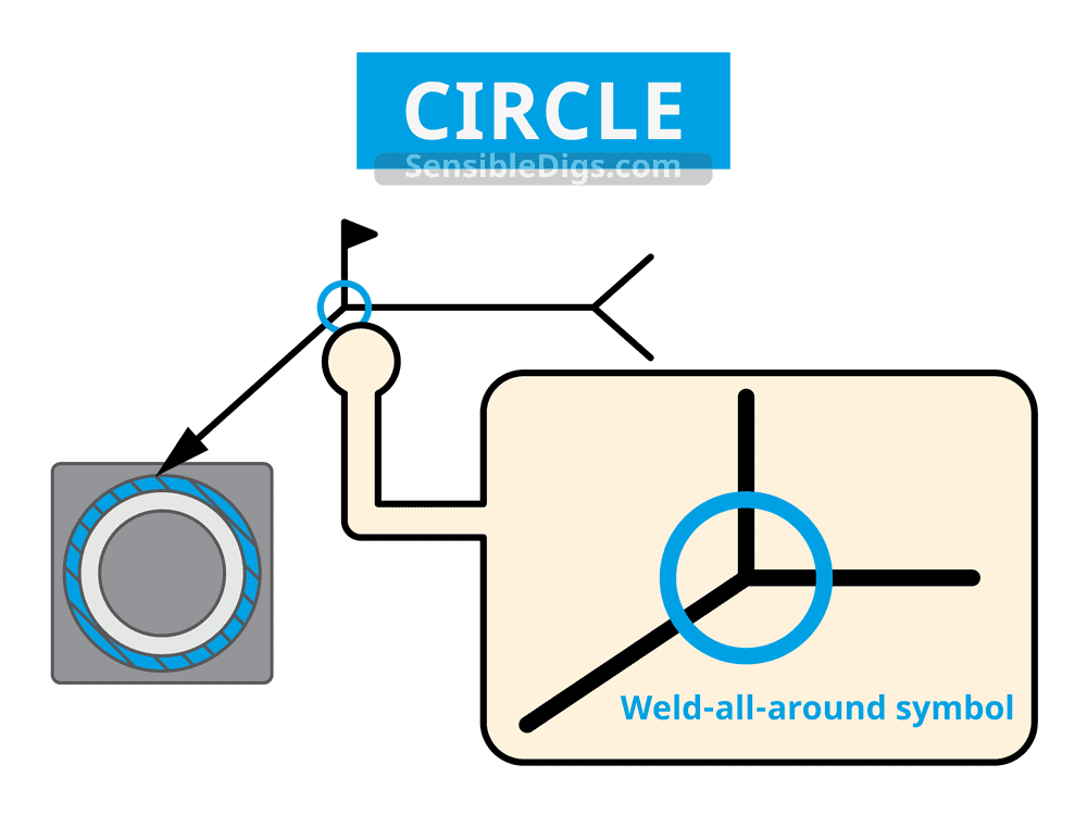
The circle tells the welder to perform a weld all around and may be used when detailing welding instructions for pipework.
Weld Symbol Vs Welding Symbol
There is a distinct difference between “weld symbol” and “welding symbol.”
- The weld symbol indicates what type of weld is required.
- The welding symbol is a way of displaying the weld symbol on drawings.
Elements of a Welding Symbol
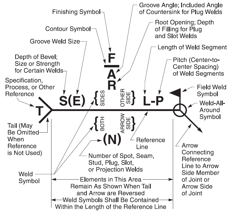
There are many elements that make up a welding symbol. What does each mark mean, and where are they located? Let’s take a look.
Arrow
The arrow denotes the side of the weld line the weld is to be performed. Sometimes there are double arrows, telling the welder that the weld can start either side of the line.
Reference Line
The reference line is the symbol that represents the weld line. It is sometimes called the leader line.
Tail
Typically, the tail is used to tell the welder specifics of the welding technique or the filler material preferred and other pertinent information. It could be something as simple as the type of welding technique required. Tails are optional.
Weld Symbols
The weld symbol indicates the type of weld required. It also tells the welder specifics, like which side the weld is meant to go.
Dimensions and Angles
Dimensions and angles tell the welder what depth of filling is needed and the angle of the countersink for plug welds.
Supplementary Symbols
Supplementary symbols tell the operator additional information like the length of the weld, the groove size, and the pitch. It also includes spacers and whether the weld is flush, concave, or convex.
Finish Symbols
Finish symbols indicate the method of the finish. G represents grinding, while M means machining. Some welding techniques require greater attention to the finish as they make more mess with spatters and slag.
Specification
Specification is the method of the weld. It is a specific instruction to the welder to create a weld that meets all the code requirements and production processes.
Process
The process can include MIG, TIG, or arc welding, to name a few of the most popular welding methods.
What Are the Basic Weld Symbols & Joints?
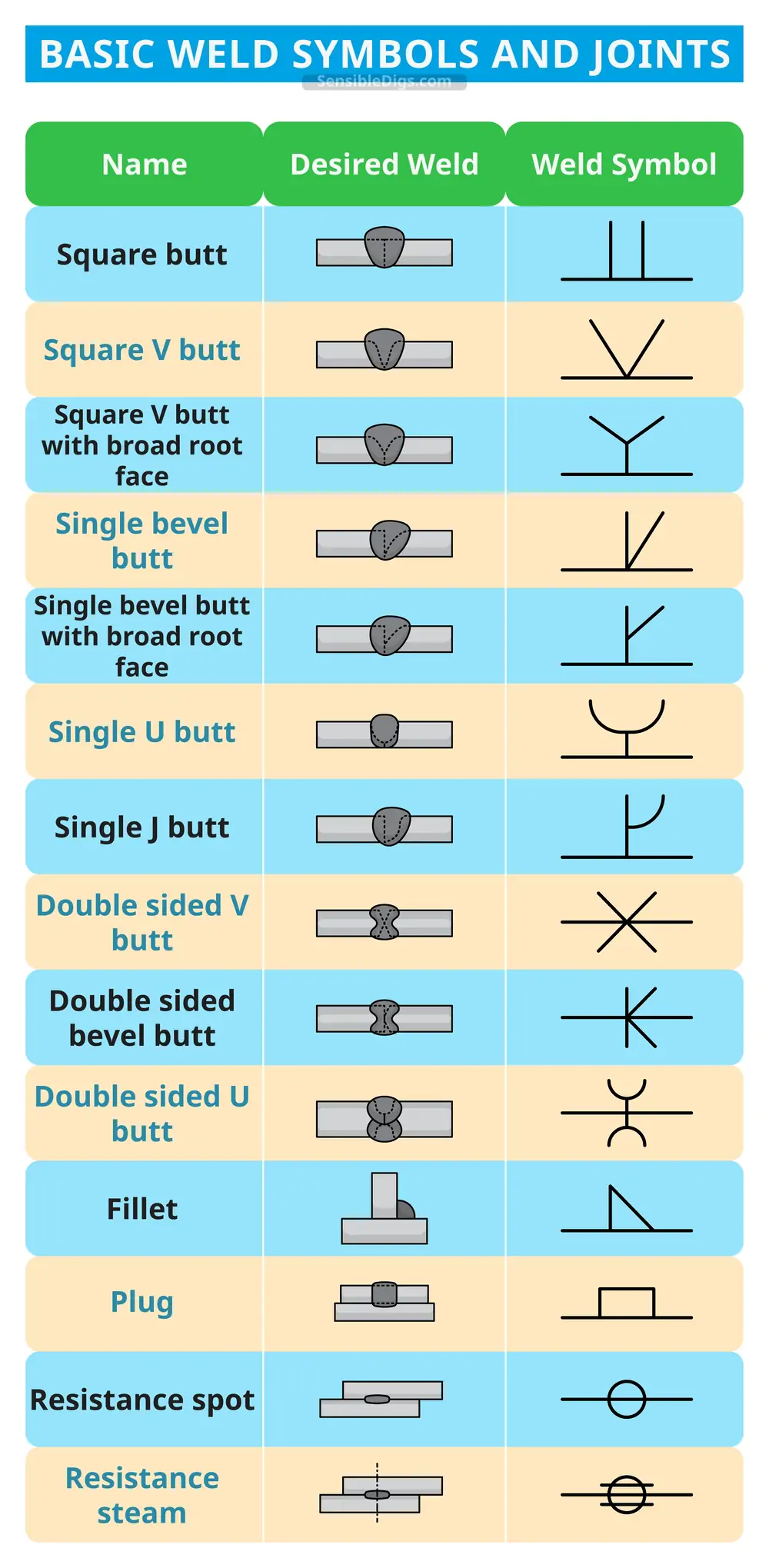
Understanding basic weld symbols and joints is crucial if you want to understand the instructions clearly.
Fillet Welds
There are 3 main types of fillet weld, with 3 variations of the fillet weld symbol. These include the arrow side, other side, and both sides. The correct location is denoted by arrows placed on the desired side of the reference line.
The weld size and length are included, as well as the pitch.
Groove Welds
Groove weld symbols tell the welder what type of groove is needed. It includes V-grooves, flare-V, U-shaped, square, and flare-bevel. The groove can go on each side of the reference line or both, depending on the specifics.
The symbol includes the depth of the bevel and the groove angle.
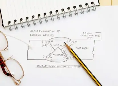
Square Groove Welds
A square groove weld is a type of butt welding joint. It has 2 pieces that are flat and parallel to each other. The symbols indicate which side the square groove joint goes. The symbol includes the dimensions of the root opening, as well as the groove weld size.
Edge-Flange
Flange weld symbols are used for lighter gauge metal joints indicating the flaring or flanging of the joint to be welded. These symbols have no arrow or side significance.
Bevel-Groove
Bevel-groove joints can be double or flare varieties, and the symbols indicate the groove weld size as well as the direction and placement of the groove. The bevel angle exists when the angle is on one of the workpieces.
Bevel welds can have flat, convex, or concave surfaces, just like fillet welds.
Corner Joint
Corner joints are when two flat sides are joined together. The arrow indicates the side the weld is to be applied to. This joint type is one of the most popular in the sheet metal industry because it is easy to perform.
Lap Joint
Lap joints are common when you want to join 2 pieces of material of varying thickness. The joint is formed when the 2 pieces are overlapped. Again, the arrow indicates where the weld is to start and on which side.
T-Joint
T-joints are formed when 2 pieces of metal are joined at 90-degree angles. T-joints are a type of fillet weld, along with the lap joint and the corner joint.
Here is a handy reference chart for all the weld symbols and joints discussed.
Understanding Welding Symbols
There are so many variations of welding symbols that it is hardly surprising that some welders lack a basic understanding. Knowing how to read these symbols shows a degree of skill that will make you stand out from the crowd.
It also makes you efficient, knowledgeable and gives you the tools to deliver an accurate and timely result.